

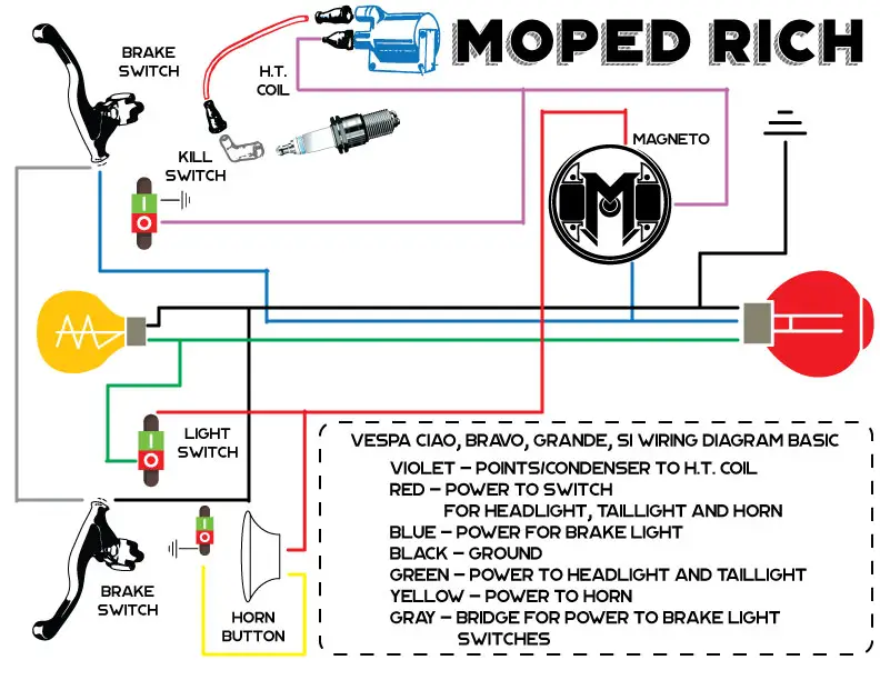
This is a simplified version of a Vespa Ciao, Vespa Bravo, Vespa Grande, Vespa Si or other vintage Vespa mopeds. This should work for most U.S. model Vespa mopeds. This is for a three wire points system without blinkers. The Vespa ignition system should only have two internal coils. If it has three coils, then its a system set up for blinkers and a battery. Check out our Mopeds for sale in Houston for Vespa moped models.
VESPA WIRING DIAGRAM – IGNITION
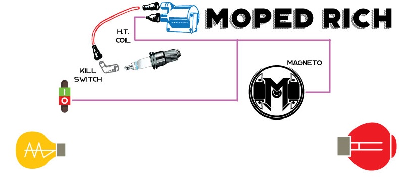
To begin we will be wiring up the external ignition coil for spark, front, and backlights. The Vespa moped engine should have two wires coming from the engine and one connector on the engine case.
Let’s start by wiring up the external ignition coil first. From the engine, there should be violet or black wire. It may look pink as well. The violet or black wire connects to the external ignition coil.
This would be a good time to hook up a kill switch. To do that, you need a basic two position switch. Connect a wire from one post or connection on the switch to the violet wire on the external ignition coil. The other connection on the switch will need to be ground out. Some switches will ground to the handlebars they mount to, others may have a wire that can be connected a ground post on the engine or to bare metal on the frame.
VESPA WIRING DIAGRAM – BRAKE LIGHT
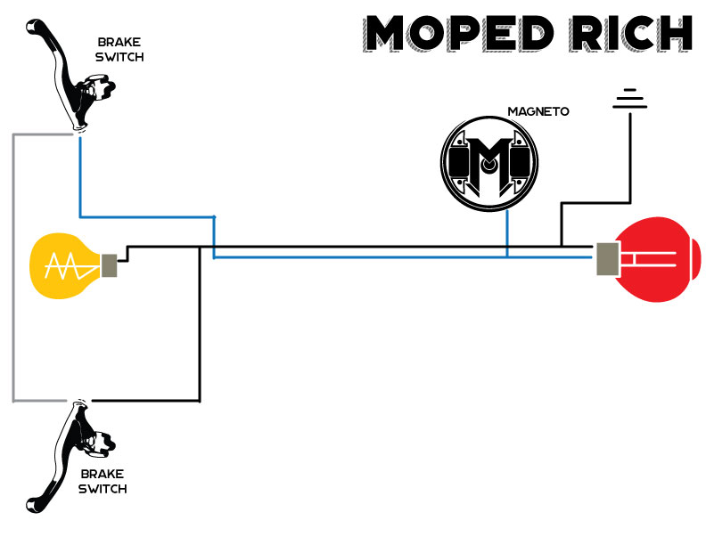
Next, we will connect the brake light. On U.S. models, the Vespa engines came with a blue wire for a brake light. Connect the blue wire from the engine to the brake light post on the rear light.
The tail light should have three posts. One post is for the running light. A second post is for the brake light. The brake light shines brighter than the running light. The last post is for the ground to complete the circuit.
Then branch off from the blue wire another blue wire to one of the posts on the right brake lever switch. Then connect a wire from the second post on the right brake lever switch to one of the post on the left brake lever switch. Finally, connect a ground wire from the second post on the left brake lever switch to complete the circuit.
It is also a safety feature for some U.S. models. If the brake light bulb burns out, the circuit will not complete and the ignition coil will not get any power from the violet wire causing the system to not provide the spark.
VESPA WIRING DIAGRAM – LIGHTS AND HORN
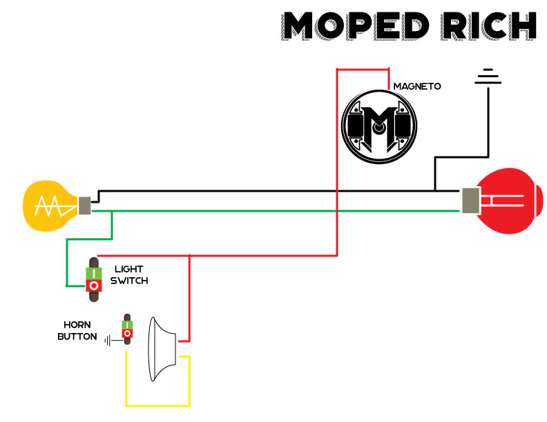
Finally, we will finish up with wiring the headlight, taillight, and horn. A switch for the lights is optional, but if wiring a horn, a button will be needed. The button will need to also ground to the handlebars or connect to the ground circuit.
There should be a male connection post on the side of the engine near the area where the blue and black or violet wire. This is the power lead for the headlight, running taillight and the horn. Connect a red wire from the engine post to one post on the horn. Connect another red wire from that same post on the horn to the switch for the lights. The green wire connects from the switch to the positive terminal on the headlight and taillight.
From the other available post on the horn, connect the yellow wire to the button used for the horn. The horn button should ground to the handlebars or the ground circuit.
The headlight and taillight will need to be connected to the ground circuit. This circuit can be created with a black wire from the ground post of each light and connected to the ground post on the engine or to bare metal on the frame.
Check out new Moped shirt designs in the shop or on Amazon


Is there a way I can run this setup on my 74 primavera 125 even though it has three internal coils? I’m not much on wiring and I’m wanting to simplify it as much as possible.
This wiring diagram works for Vespa 50cc mopeds. I’m not sure how the wiring differs for the Vespa scooters.
Hello am redoing a 1973 vespa with out turn signals and looking figure out wiring the bullet headlamp two positions key so can use that as a from of security you have any diagrams how that is suppose to be done with the lights staying on once turn the key to on and of course it’s running
Sorry, I do not. Ill need too make one.
where is the ground connection to the body located?
The connection is on a bolt at the top of the engine near the connection for the lights. The first bolt nearest the cylinder. Its a copper tab held by that nut and bolt.
What wires hook to the two engine clips on a 196l77 Vespa btavo and where dpes thr red horn wire button hook up?
If the original wiring is there, on a Vespa Bravo, the Black wires from the harness would connect to the brass “engine ground” connector that is held in place by a case bolt. The Red wire from the original harness would connect to a male terminal that should have some plastic protecting it. That connector will be poking out the engine near the rubber grommet for the other two engine wires. The original horn has two connections on the back, the red goes into one of those connections. I don’t think it matters which one but you may need to test it.
We 1973 ciao it’s the model super comfort it was supposed to have turn signals and a battery somebody bypass the turn signal is completely took them off the bike so I was looking to wire it all back up inside the headlight there’s like a circuit board how do you wire up the circuit board without a battery and turn signals I found your diagram but I can’t figure out the switch that’s there already
Sorry Jamie, I haven’t had to rewire turn signals yet. I usually remove them as well. I believe they require a battery to run the signals.